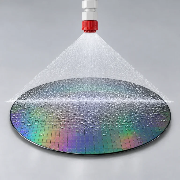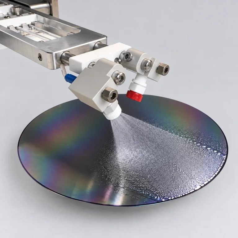
Heat aqueous developing and cleaning solutions during dispensing. The Cee® In-Line Dispense Heater adds recipe-defined temperature control and real-time monitoring through DataStream™.
Requires a separate dispense system. The heater installs in line with your existing dispense system to add temperature control during dispensing.
Select a heater line size.
Use the flow chart to confirm viscosity and pressure. Heating capacity is approximately 500 mL/min from room temperature to 80°C; nozzle restrictions can reduce flow.
Add heated aqueous dispensing to a compatible Apogee® developer configuration. Installed between the liquid source and dispense valve, the heater raises the temperature of the solution during delivery for developing and cleaning semiconductor substrates.
Set dispense temperatures in the DataStream™ recipe and monitor actual and setpoint temperatures in real time. Heating starts when dispensing is triggered and liquid begins to flow. The interface accommodates multiple in-line heaters, with temperatures defined independently for each heater.
The adjustable setpoint range is 20°C to 80°C. The heater raises liquid temperature above ambient and does not provide cooling.
For compatible Apogee® spin developers configured for heated aqueous dispensing. Install the heater in line with an existing compatible aqueous dispense system. Cee® can confirm the equipment connection and material compatibility for your application.
The heater adds temperature control to an existing compatible aqueous dispense system. A separate dispense system is required.
A typical arrangement is material source → in-line heater → dispense valve → tip or spray nozzle. Use a pressure can, a House Source, or another compatible supply configured for the application. Explore Fixed Spray Dispense or AccuScan™ Spray Dispense for the delivery configuration.
Tell Cee® your developer model, aqueous chemistry, desired dispense temperature, flow requirements, and delivery method. Confirm chemical compatibility throughout the wetted path and select the appropriate ⅛″ or ¼″ OD fluid connections.
Connect the heater to the Apogee® equipment for communication and to the existing dispense system for its pneumatic trigger. The heater also requires its own electrical supply. Mount vertically with the outlet upward and keep the tubing from the heater to the dispense valve as short as practical.
Use these typical system planning flows, including the dispense valve, to compare line size, viscosity, and pressure. Start with the ⅛″ heater for flows up to 340 mL/min or the ¼″ heater for higher flows, then confirm the required flow against the table.
Scroll across the table to compare line sizes and pressures.
| Viscosity | ⅛″ lineSKU# 903610 | ¼″ lineSKU# 903987 | ||
|---|---|---|---|---|
| 10 psi | 15 psi | 10 psi | 15 psi | |
| 1 cP | 270 mL/min | 340 mL/min | 1,100 mL/min | 1,400 mL/min |
| 2 cP | 270 mL/min | 330 mL/min | 1,000 mL/min | 1,300 mL/min |
| 3 cP | 210 mL/min | 300 mL/min | 1,000 mL/min | 1,300 mL/min |
| 4 cP | 160 mL/min | 230 mL/min | 1,000 mL/min | 1,300 mL/min |
| 5 cP | 130 mL/min | 190 mL/min | 1,000 mL/min | 1,300 mL/min |
| 6 cP | 110 mL/min | 160 mL/min | 930 mL/min | 1,200 mL/min |
| 7 cP | 95 mL/min | 140 mL/min | 840 mL/min | 1,100 mL/min |
| 8 cP | 83 mL/min | 120 mL/min | 760 mL/min | 1,000 mL/min |
| 9 cP | 74 mL/min | 110 mL/min | 700 mL/min | 1,000 mL/min |
| 10 cP | 67 mL/min | 100 mL/min | 650 mL/min | 920 mL/min |
Heating capacity: Approximately 500 mL/min from room temperature to 80°C. These system flow estimates are separate from heating capacity; plan heated delivery around the lower limit.
Not included: The separate dispense system. The heater installs in line with an existing compatible system.
20°C to 80°C
Compatible aqueous developing and cleaning solutions
Recipe-defined and real-time monitoring through DataStream™
On demand during triggered dispense flow
Approx. 0.5 L/min (500 mL/min), room temperature to 80°C. Delivery also depends on the configured fluid path.
10 lb (4.54 kg)
W: 8″ (203 mm)
D: 3½″ (89 mm)
H: 14½″ (368 mm)
208–230 VAC, single phase, 50/60 Hz
2,755 W (12 A)
⅛″ OD pilot connection to the existing dispense system
⅛″ or ¼″ OD, as configured
M8, 4-pin connection to Apogee® equipment
Vertical mounting with the outlet pointing upward
Need a special delivery method or a configuration you don’t see here? Cee® offers custom solutions built around your material, equipment, and process.
See examples of our custom equipment, then contact Cee® to discuss your dispense requirements.
SEMICON EUROPA · 10–13 NOVEMBER
Meet Jacob, CEE’s Global Sales Director, in Munich with our partner SiSTEM Technology.
Stand C1353 · Messe München
Spin coating, bake and chill, temporary bonding and debonding.
Mention Jacob from CEE in SiSTEM’s booking form.