Wafer Bonding Theory
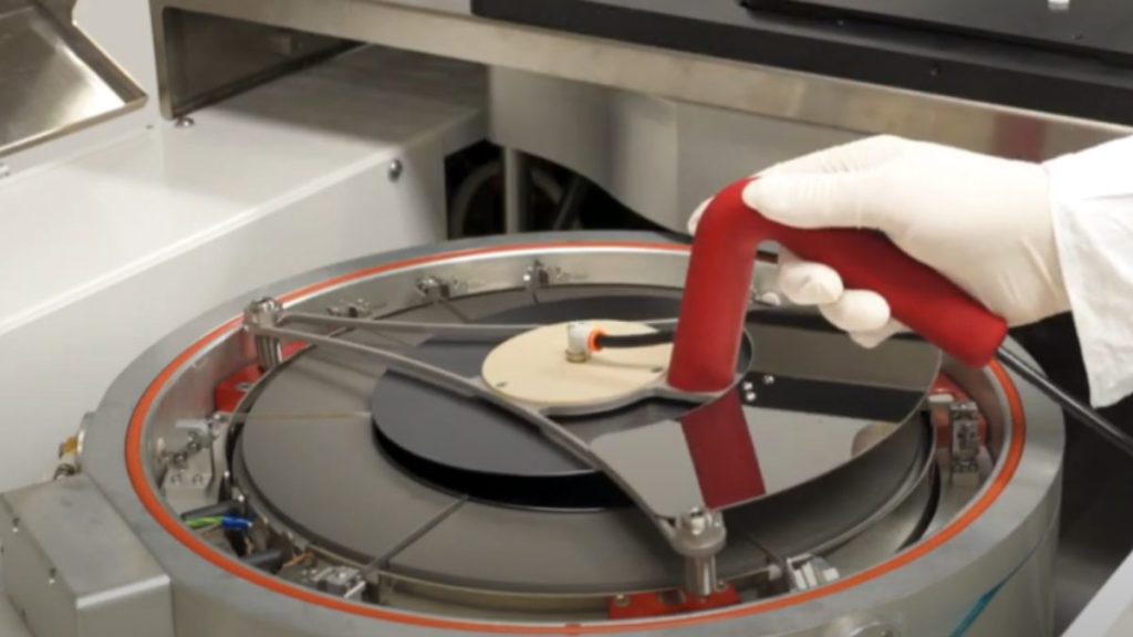
Wafer bonding is crucial for compact and powerful devices. It involves coating a full thickness wafer with adhesive, bonding it to a support carrier wafer, and thinning it for downstream processes. Key factors impacting bonding quality include flatness (TTV), alignment, voids, temperature control, CTE match, and bonding force. Addressing these factors ensures uniform bonding, precise […]
Megasonics
The Megasonic Method A semiconductor manufacturer faced challenges cleaning intricate structures on substrates. Conventional methods were inadequate, causing defects and lower device performance. Cee® suggested using megasonic technology, utilizing high-frequency sound waves to remove contaminants effectively. We chose the ProSys Stainless Steel MegPie™ transducer for its precision and adaptability, integrated with DataStream Software for process […]
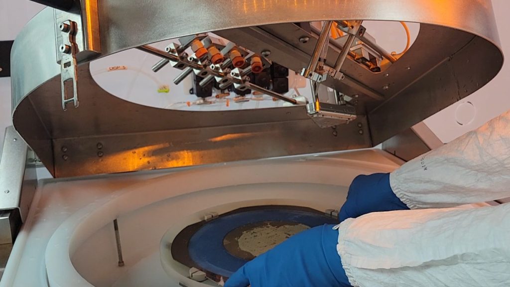
Automated Dispense Systems

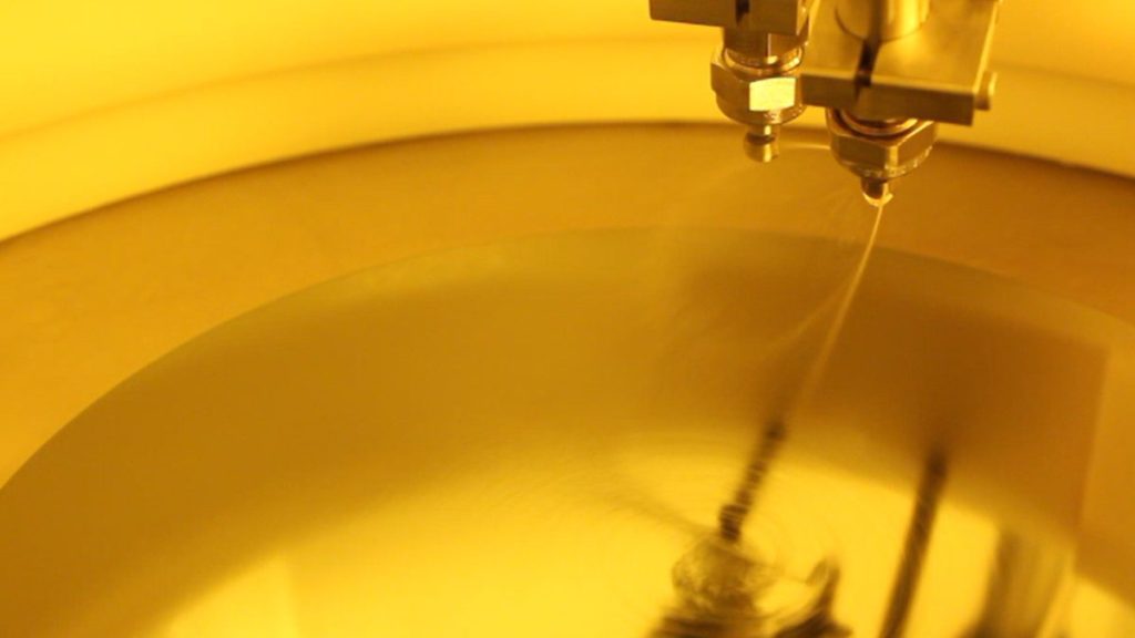
This article explores automated dispense options for spin coating applications in the semiconductor industry including cartridge dispense, pressure can dispense, and disposable syringe dispense. The article also touches on dispense controls, edge bead removal, and backside rinse, while highlighting the benefits of the Cee® line-up of Apogee® Spin Coaters. Automated Dispense Systems Spin coating is […]
Nitrogen Purge
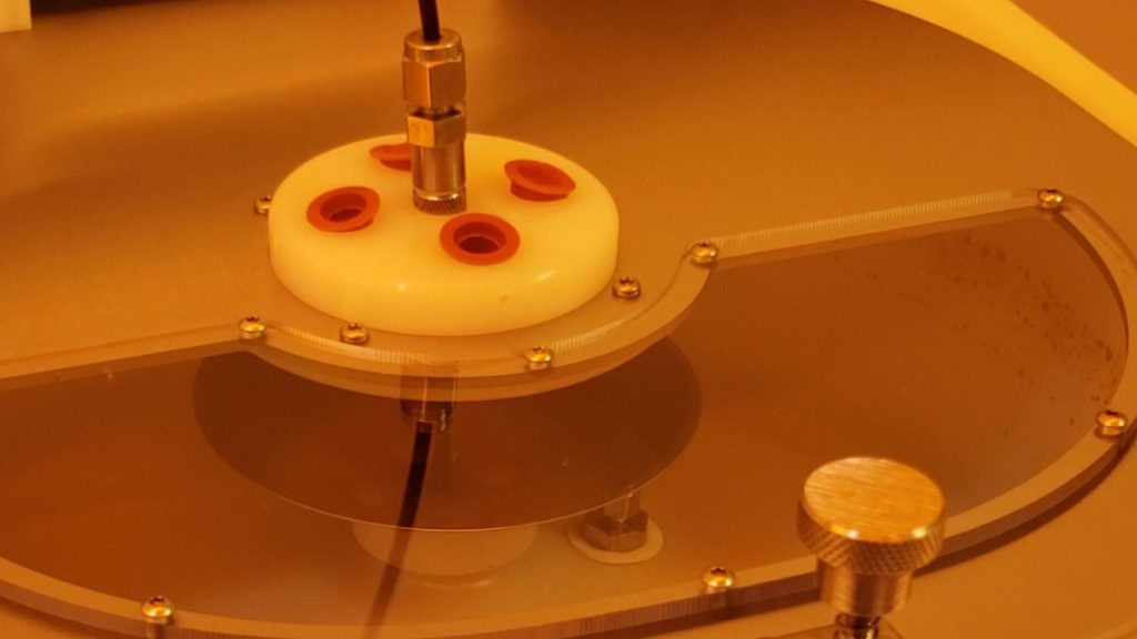
Nitrogen purge is widely employed in the manufacturing of semiconductors. It is utilized to establish a low-oxygen setting for processing substrates. This method helps remove impurities, minimize oxidation, maintain uniform film deposition, and can be beneficial for meeting safety standards. Nitrogen Purge Nitrogen purge is a common technique used in various industries, including semiconductor manufacturing, […]
Accessories
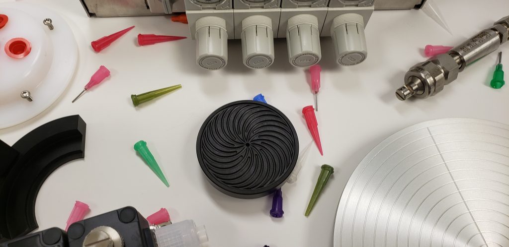
Accessories Accessories Blog Home Spin Bake Develop Accessories Blog Home Spin Bake Develop Accessories Accessories Spin Automated Dispense Systems July 20, 2023 Accessories Bake N2 Purge Spin Nitrogen Purge July 5, 2023 Accessories Bake Multi-Stage Baking with Programmable Lift Pins March 20, 2023 Develop Spin Spin Chucks Spin Chucks for Square Substrates March 17, 2023 […]
Develop
Develop Develop Blog Home Spin Bake Develop Accessories Blog Home Spin Bake Develop Accessories Develop Developer Configurations March 20, 2023 Develop Spin Spin Chucks Spin Chucks for Square Substrates March 17, 2023 Develop Spin Spin Chucks Spin Chucks for Thinned Substrates March 17, 2023 Develop Spin Selecting Maximum Spin Speed and Acceleration March 17, 2023 […]
Bake
Bake Bake Blog Home Spin Bake Develop Accessories Blog Home Spin Bake Develop Accessories Accessories Bake N2 Purge Spin Nitrogen Purge July 5, 2023 Bake Bake Plate Process Theory March 21, 2023 Accessories Bake Multi-Stage Baking with Programmable Lift Pins March 20, 2023
Spin Coat
Spin Coat Spin Coat Blog Home Spin Bake Develop Accessories Blog Home Spin Bake Develop Accessories Accessories Spin Automated Dispense Systems July 20, 2023 Accessories Bake N2 Purge Spin Nitrogen Purge July 5, 2023 Spin The Cotton Candy Effect March 22, 2023 Develop Spin Spin Chucks Spin Chucks for Square Substrates March 17, 2023 Develop […]
The Cotton Candy Effect
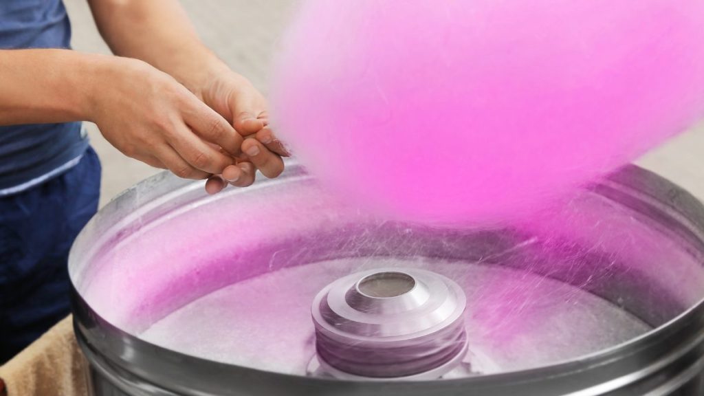
The cotton candy effect is a common issue in the semiconductor manufacturing process where dried material comes off the substrate in string-like filaments instead of droplets. To address this issue, process parameters and environmental factors should be adjusted. Optimization testing is required to fine-tune the process until the cotton candy effect is eliminated. The Cotton […]
Bake Plate Process Theory
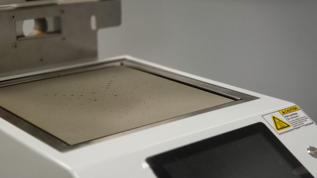
Hotplate baking is a popular technique for film drying and curing, offering advantages over traditional convection ovens such as decreased bake time, increased uniformity, reproducibility, and decreased particle contamination. Hotplate baking heats the substrate from the bottom up, preventing the formation of a skin on the film surface and offering advantages for thick films. Bake […]