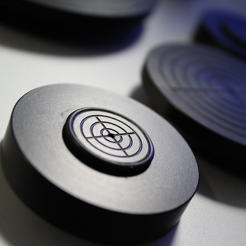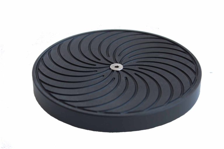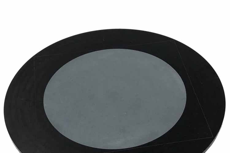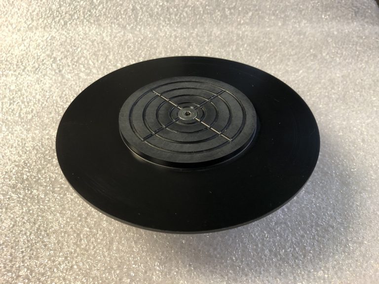
Captive Spin Chucks are typically recommended for developing and cleaning substrates that need a geometry matched to their shape. Captive arms locate the specified substrate and provide lateral support during the process.
Each captive chuck is custom made for your substrate dimensions and process requirements.
SKU unavailable — custom made to order.
Spin coating a rectangular substrate?
Captive Spin Chucks hold square, rectangular and other specified substrates within a dedicated arrangement of supports. They are typically used for developing and cleaning, where corner coating uniformity is less critical or the process allows an exclusion area. Vacuum or mechanical holding can be used, depending on the supplied configuration.
The captive arms locate a correctly loaded substrate and provide lateral support, so a separate centering device is not needed for the matched arrangement. The open support geometry typically requires less cleaning than a recessed chuck because there is less chuck material. Both designs are designed to minimize backside contamination, with results dependent on the process.
|
Comparison
|
Recessed Chuck
|
Captive Chuck
|
|---|---|---|
|
Typical processes
|
Spin coating
|
Developing and cleaning
|
|
Corner uniformity
|
Emulates a round wafer to improve coating uniformity at corners and edges
|
Typically used when corner coating uniformity is less critical or the process allows an exclusion area
|
|
Substrate retention
|
Vacuum pad
|
Vacuum or mechanical holding, depending on configuration
|
|
Cleaning
|
More surrounding chuck material to clean
|
Typically requires less cleaning because there is less chuck material
|
|
Backside contamination
|
Designed to minimize backside contamination; results depend on the process
|
Designed to minimize backside contamination; results depend on the process
|
Provide the substrate drawing, dimensions, thickness, material and weight when available. Identify the allowed edge and backside contact areas, developing or cleaning chemistry, Cee tool model and intended recipe conditions.
Available construction materials include Delrin®, PVDF, PTFE, stainless steel, PEEK and anodized aluminum. Select the material and holding arrangement together with chemical compatibility and substrate-contact requirements. Specify vacuum or mechanical holding as part of the configuration.
The arms and contact areas are made for the specified piece rather than serving as a universal adjustable holder. Keep the matched substrate and chuck together, and use the supplied installation, loading and removal procedures.
Specified substrate shapes and sizes
Developing and cleaning
Captive arms and lateral support
Vacuum or mechanical holding; confirm supplied configuration
Matched to the specified Cee tool
Defined for substrate and process