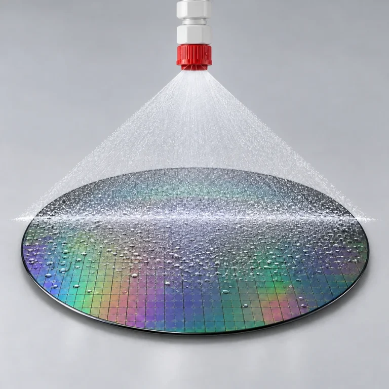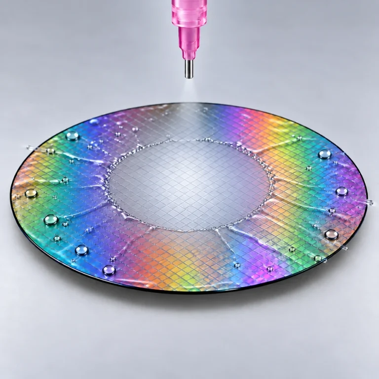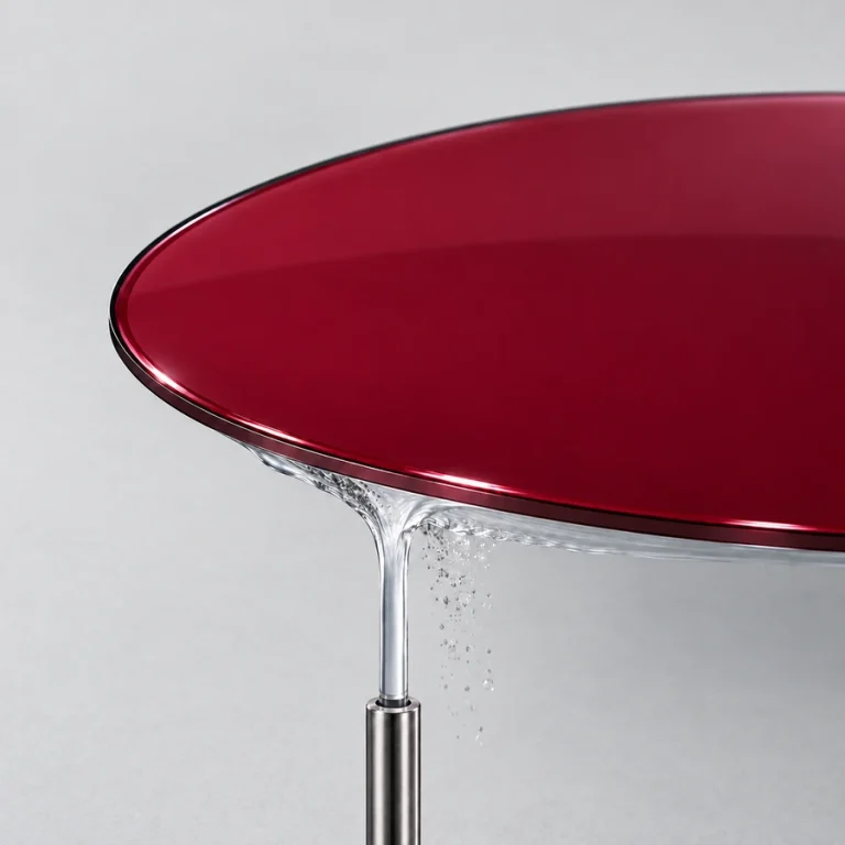
Precisely position and scan a fan spray for demanding developing and cleaning processes, including metal liftoff and high aspect ratio applications. AccuScan™ gives you recipe control over where the spray lands, how it moves, and when it dispenses.
Requires a dispense control box, sold separately. One box supports up to four dispenses. Need more than four? Add dispense control boxes to expand your system.
All configurations use a ¼″ liquid line and valve with AccuScan™ fan-spray delivery. This SKU identifies the pressure-can spray supply; the AccuScan™ arm and dispense control box are ordered separately.
The AccuScan™ arm moves fan-spray delivery across the wafer under DataStream™ recipe control. Set the spray position and movement for the process, hold a selected location, or pre-dispense off the wafer before bringing fresh liquid onto the substrate.
Controlled impingement and targeted delivery support residue removal, surface wetting, metal liftoff, and other demanding cleaning applications. Tune the chemistry, flow, scan motion, timing, and spin conditions together for the substrate.
The developer arrangement accommodates up to two liquid dispenses plus N₂ blow-off. Combine the selected spray steps with a drying step in one recipe. The arm parks clear of the wafer between uses, helping manage residual liquid at the nozzle.
Configure each spray supply with a 1–10 gallon pressure can, standard stainless-steel or PFA-coated finish, and a ¼″ liquid line and valve. Empty-reservoir float sensing supports supply monitoring through DataStream™. The dispense control box is required for automated pneumatic delivery and is ordered separately.
Select a 1, 2, 3, 5, or 10 gallon pressure can and either standard stainless steel or PFA-coated construction. Every option shown here uses a ¼″ liquid line and valve. PCBE identifies a standard vessel, PCBTE identifies a PFA-coated vessel, and the ASDS suffix identifies AccuScan™ spray delivery.
X-Pro pressure can storage: 1- and 2-gallon pressure cans fit inside the X-Pro in the designated storage area. Pressure cans larger than 2 gallons must be located outside the X-Pro.
For example: PCBE-1-2-ASDS. The displayed SKU identifies the pressure-can spray supply. Specify the AccuScan™ arm and compatible developer installation separately.
Confirm the Apogee® developer model, substrate geometry, chemistry, scan positions, speed, and number of liquids. Allow space for the arm and access to the reservoir lid. If the process includes gas drying on the arm, select N-1-AS on the N₂ Blow-Off Dispense page.
The spray supply is ordered separately from the arm. Each selected pressure-can supply includes:
Purchased separately: The dispense control box and any N₂ blow-off dispense.
0.1 mm
0–50 mm/s
Up to two liquid dispenses plus N₂ blow-off
¼″
Up to 100 cps
Standard stainless steel or PFA-coated
9″ (228.6 mm) beyond standard equipment depth
2″ (50.8 mm) above standard equipment height
1, 2, 3, 5, or 10 gallons
Pressure-can reservoir dimensions are shown below. Allow access to the lid and connections.
1 gallon
11.5″ (29.2 cm)
10″ (25.4 cm)
2 gallons
14.5″ (36.8 cm)
10″ (25.4 cm)
3 gallons
18″ (45.7 cm)
10″ (25.4 cm)
5 gallons
25″ (63.5 cm)
10″ (25.4 cm)
10 gallons
28″ (71.1 cm)
13″ (33.0 cm)
Allow at least 12″ (30.5 cm) above the reservoir for access to the lid and top components.
Nitrogen or clean dry air
70 psi to the dispense control box
DataStream empty-reservoir float sensor
Need heated dispensing, a special delivery method, or a configuration you don’t see here? Cee® offers custom solutions built around your material, equipment, and process.
See examples of our custom equipment, then contact Cee® to discuss your dispense requirements.
SEMICON EUROPA · 10–13 NOVEMBER
Meet Jacob, CEE’s Global Sales Director, in Munich with our partner SiSTEM Technology.
Stand C1353 · Messe München
Spin coating, bake and chill, temporary bonding and debonding.
Mention Jacob from CEE in SiSTEM’s booking form.