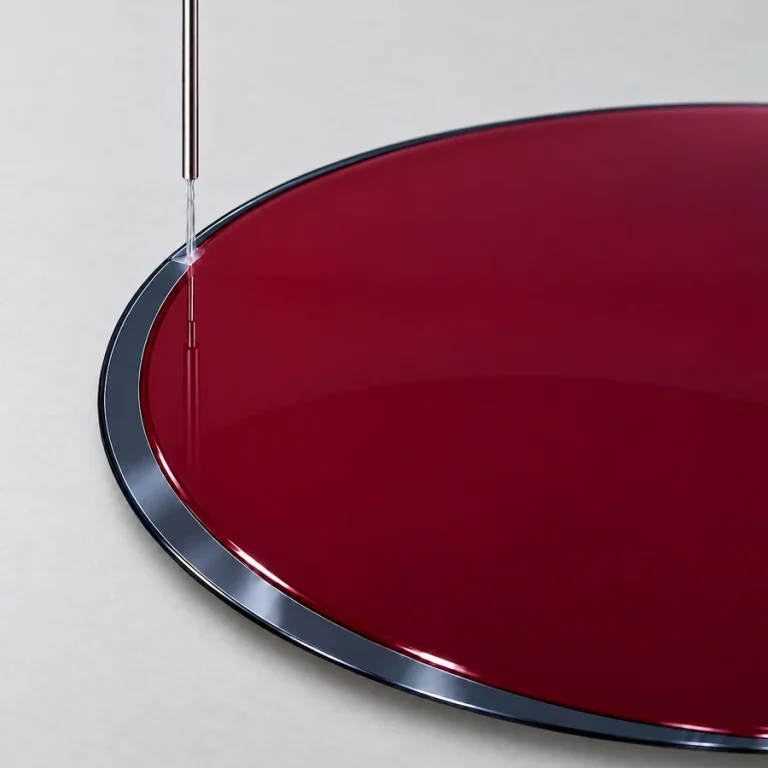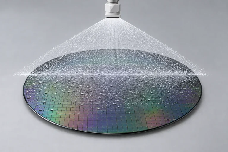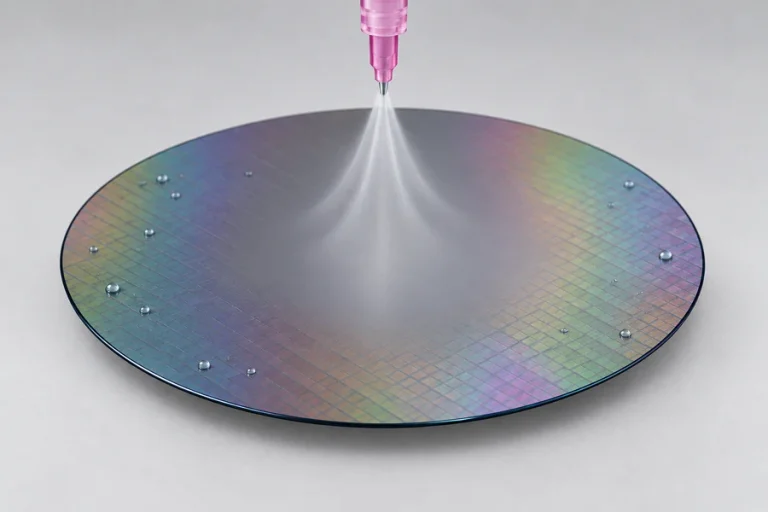
Backside rinse supplies liquid from a pressure can to an upward-facing nozzle beneath the spinning substrate. It removes unwanted process material from the back side of the wafer, with rinse timing integrated into the DataStream recipe.
Requires a four-position dispense control box, sold separately. One box supports up to four dispenses. Need more than four dispenses? Add four-position dispense control boxes to expand your system.
⅛″ dispense line and valve · Backside rinse nozzle · no suckback
Select your configuration.
Backside rinse directs a compatible liquid upward onto the underside of a spinning substrate. It washes away photoresist, developer solution, or other process material carried onto the back side, helping reduce residue transferred to later handling and process surfaces.
The rinse is supplied from a separate pressure can through a dedicated ⅛″ valve and line. Reservoir size and vessel finish are selected around liquid usage, refill frequency, and chemical compatibility.
Nozzle position, flow, recipe timing, and spin conditions work together to rinse the intended area. DataStream coordinates the rinse step with the tool process.
The backside-rinse valve has no suckback control. With the nozzle directed upward, gravity handles drainage after the dispense stops. An installed float sensor monitors the pressure-can supply through DataStream; the dispense control box is required and sold separately.
Select a 1, 2, 3, 5, or 10 gallon reservoir and either a standard stainless-steel or PFA-coated vessel. Confirm the compatibility of the complete wetted path with your rinse liquid.
X-Pro pressure can storage: 1- and 2-gallon pressure cans fit inside the X-Pro in the designated storage area. Pressure cans larger than 2 gallons must be located outside the X-Pro.
The selector combines vessel type and capacity with the fixed ⅛″ line code and BSR outlet. Standard vessels use the PCBE prefix; PFA-coated vessels use PCBTE. For example, a standard 1-gallon system is PCBE-1-1-BSR. Every option on this page uses a ⅛″ line and valve.
Specify your Cee spin coater or developer model, substrate size, process chemistry, and backside cleanliness requirements. Confirm the substrate-holding arrangement and bowl-nozzle position so rinse liquid reaches the intended area. The rinse line connects at the tool’s rear utility bracket, then feeds the nozzle through the bowl connection. Adjust flow and timing for the material; backside rinse does not use suckback.
A dispense control box is required and sold separately. One box supports up to four dispenses; additional boxes expand the system beyond four.
The float sensor is assembled onto the pressure can for supply monitoring through DataStream.
Backside rinse uses an upward-facing nozzle and no suckback control; gravity handles drainage after dispensing.
Purchased separately: The dispense control box.
1–10 gal / 3.7–37 L
Standard stainless steel or PFA-coated
PFA, PTFE, 304/316 stainless steel
⅛″
Upward-facing bowl nozzle; position adjustable
No suckback control; gravity handles drainage
Dimensions below apply to the pressure-can reservoir. The nozzle installation is matched to the Cee tool.
1 gallon
11.5″ (29.2 cm)
10″ (25.4 cm)
2 gallons
14.5″ (36.8 cm)
10″ (25.4 cm)
3 gallons
18″ (45.7 cm)
10″ (25.4 cm)
5 gallons
25″ (63.5 cm)
10″ (25.4 cm)
10 gallons
28″ (71.1 cm)
13″ (33.0 cm)
Allow at least 12″ (30.5 cm) above the reservoir for access to the lid and top components.
Nitrogen or clean dry air
70 psi to the dispense control box
DataStream empty-reservoir float sensor
Need heated dispensing, a special delivery method, or a configuration you don’t see here? Cee® offers custom solutions built around your material, equipment, and process.
See examples of our custom equipment, then contact Cee® to discuss your dispense requirements.